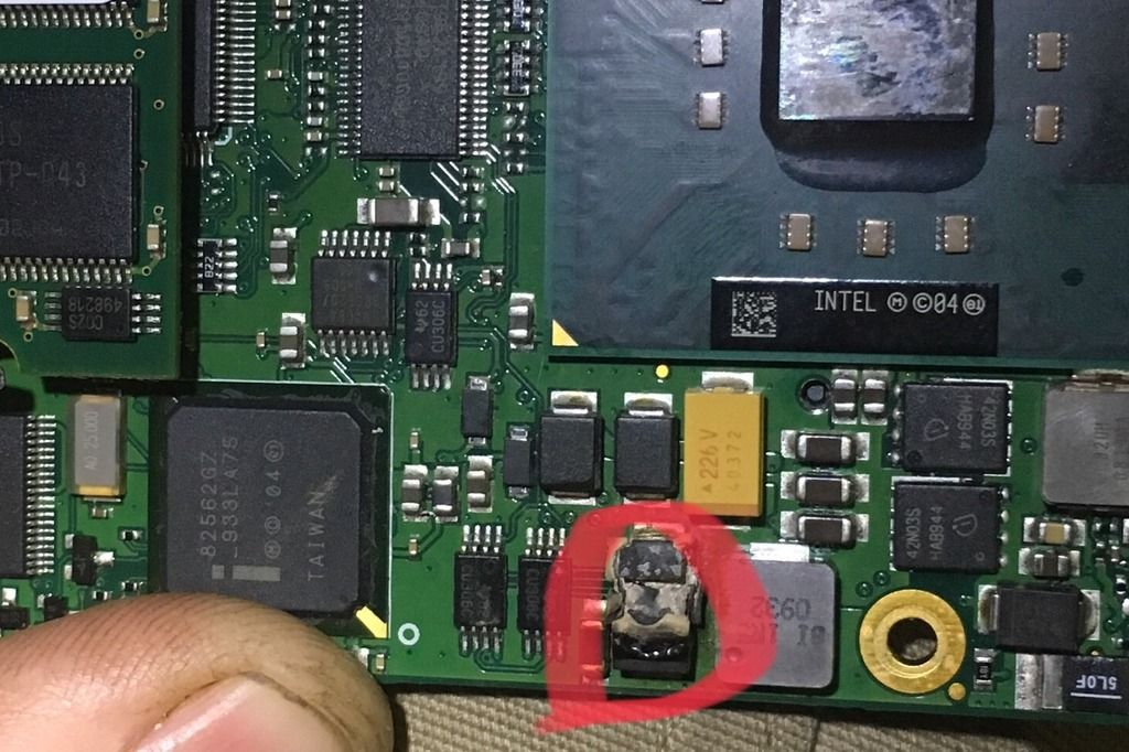
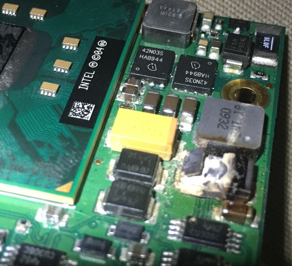
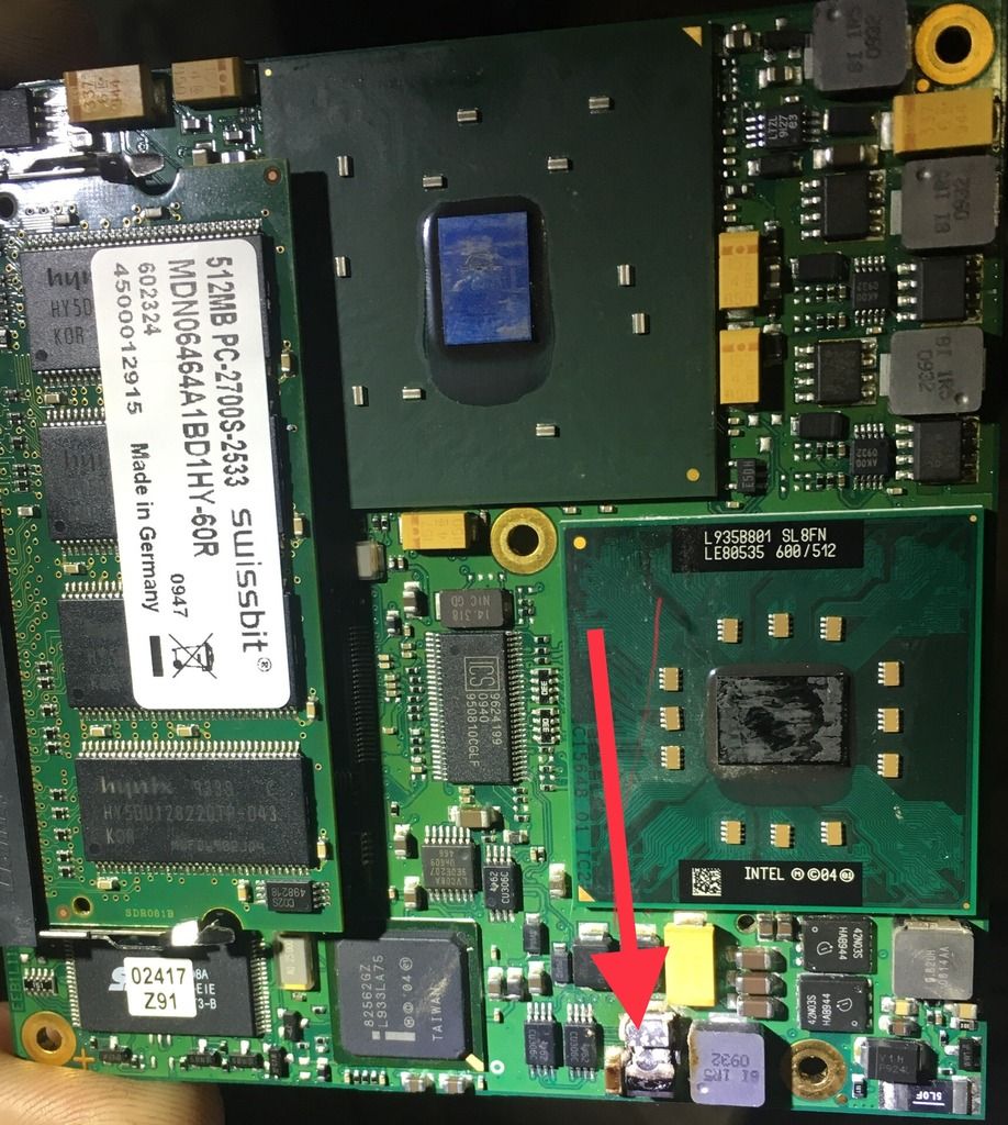
I acquired a non working Verus I believe I have found out why. Little back story for fun is that this unit would power up but no screen activity. Well I took it all part to get to the hard drive to make sure it was good. I was able to put it in my gaming computer as a second drive and see it and run files on it so the drive is good just could not boot from it. I found out later about the encryption on these things. Also seen about a bad ram chip would also give a no boot. When I started looking there I found a chip that is exploded we’ll say. Now I believe this chip would have been a chip that had a 226v 40372 writing on it. Just judging by size and shape so I have no way of confirming this so that where I need the help. And maybe where I could get one.
Chipset repair
Collapse
X
-
Originally posted by John LansfordWell first you have to determine whether this is 2 pins or more?
Originally posted by John LansfordIs this under the CPU Heatsink/Fan?
Originally posted by John LansfordCould the part number be 220 not 226?
Originally posted by John LansfordThe letters in this series are A, B, C, CA, Y, Z
The soldering iron I have will not unsolder the chip. I guess it won’t get hot enuff. It old. So I can’t look under it and see enything. I’ve had other failed projects due to that thing so I’ll be looking into a new one.Comment
-
I was wrong in my post about the chip being a TVS. The way it exploded and the black coloring in the photo made me think it was similar to my problem.
The capacitor nearby is a 22uF 40Volt Capacitor.
These chips are difficult to unsolder because of the non-lead solder.Last edited by John Lansford; 09-13-2018, 03:42 AM.Comment
-
In last nights reading I found where there thing come from. I believe it’s made by avx.com
I can match up the logo 226 and the V but the 40372 is still a question.
I put a email in to them so we’ll see what happensComment
-
-
That is a capacitor in the Switch Mode Power Supply Circuit.
Wonder what other devices might have blown along that path?
You said the Screen is black?Comment
-
Well I ordered what I thought was going the right thing. It is for sure not the same.
I’ve update link to go to the right one
But what I did learn no matter what way you flip it and I even tried just putting a jumper in and it did not change anything but when I put a jumper in it would just give a power light no WiFi light or fans.Last edited by Tkempt200; 09-22-2018, 06:02 PM.Comment
-
I believe that is the correct part.
also remember to use correct polarity.
The end with the dark line is the anode or positive end.
You said you were having problem removing capacitor from board.
I use both flux and extra 60/40 solder to the area to help with melting the old solder.
There may be more parts bad they don't all necessarily have to blow up to be damaged.Comment
-
The part is not the same size nor does it have the V. It has T. As far as other parts being bad I’m not sure how I’d determine that. Did use a small led as a test light and could get it to light up on one side but not the other with the new chip.Comment
-
You have to measure SMD parts to get the right size.
You are finding out how hard it is to fix electronics without a circuit diagram.
If you look at my repair of the charger circuit you only see the chips that are cracked or exploded but I changed a TVS that looked perfectly fine also.
Sometimes you can look at the chips surrounding the bad capacitor and measure them for shorts or opens.
There are diodes and MOSFET switching transistors in that area. Like I said some sort of DC-DC power circuit.
Did you pay a lot for the Verus unit or did you get it very reasonable?Comment
Comment